Defined through minimum thickness → required hours
Topcoat indication
Optional (organic/inorganic) written text
T1, T2, T3, T4 classification for paints, sealants, lubricants
Lubrication indication
flZnL includes lubricant in the system
Lubrication indicated only if T4 topcoat is used
Overall designation examples from standard
bolt M8 ISO 4014 - flZnL/nc/720h
Fe/iflZn4/yc Fe/[SR(210)3]/pflZn8/nc/T2
8. Component Type & Application Restrictions
Topic
ISO 10683
EN 13858
Threaded fasteners
✔ Included
✘ Excluded
Non-threaded parts
✔ Included
✔ Included
Complex geometry
Bulk or rack selection guidance
Immersion ensures full coverage
Temperature restrictions
Curing must not affect fastener hardness
Should not be used above curing temperature
9. Additional Tests
Test Type
ISO 10683
EN 13858
Torque-Clamp Force
Included for fasteners (ISO 16047)
Not included
SO₂ (Kesternich Test)
For building fasteners only
Not included
Adhesion
Mandatory for both
Ductility tests
Defined for fasteners (7.4)
Not required
Sampling rules
Detailed in ISO 3269
1% sampling; batch rejection rules
10. Summary Table – Quick Differences
Feature
ISO 10683
EN 13858
Main use
Fasteners
All steel parts except fasteners
Thickness
Reference
Mandatory minimum
Lubrication
Strong focus (fastener torque)
Optional topcoat lubricants
Salt spray
240-960 h
240-960 h (higher thickness for nc coatings)
Designations
Based on fastener order system
Based on component/coating sequence
Extra tests
Torque, ductility, SO₂
Adhesion, thickness
Mega-Table: ISO 10683 (fasteners) vs EN 13858 (components except fasteners)
Topic
ISO 10683 (fasteners)
EN 13858 (components-excluding threaded fasteners)
Scope / Applicability
Applies to non-electrolytically applied zinc-flake coating systems for steel fasteners (bolts, screws, studs, nuts, washers, pins, clips, etc.). Not for mechanically applied zinc coatings.
Applies to non-electrolytically applied zinc-flake coatings on iron/steel components excluding threaded fasteners. Notes on curing temperature vs service temperature.
Purpose / Focus
Fastener-specific requirements: torque/clamp force, ductility for assembly, tests relevant to fasteners; IHE risk management for high-strength fasteners.
General corrosion protection requirements for components; process guidance (immersion vs spray), minimum local thickness requirements and sampling/adhesion tests.
Dip-spin or spray; bulk or rack coating; cure temperatures can be up to 320 °C (must not exceed tempering of quenched & tempered fasteners). Emphasis on process selection for fastener geometry.
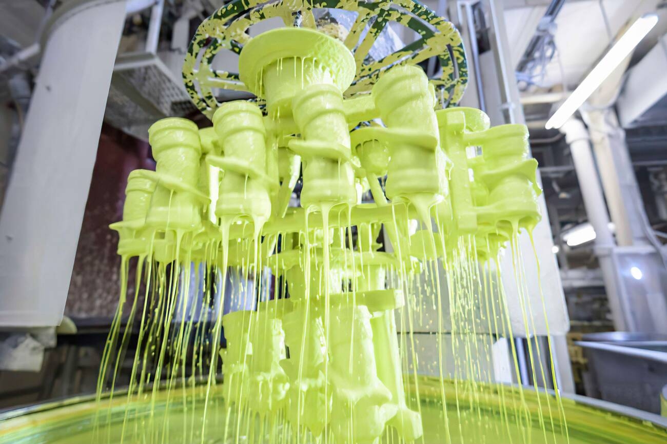
Immersion (cold) or pneumatic/electrostatic spraying (selective). Immersion gives full coverage; curing typically >180 °C for 15-60 min.
Pre-treatment & IHE (hydrogen embrittlement)
Specific guidance to avoid internal hydrogen embrittlement (IHE): mechanical cleaning preferred; acid pickling allowed only with inhibitors and limited exposure; phosphating permitted as alternative; cathodic cleaning forbidden. Special rules for hardness >390 HV / property class 12.9+.
Recommends mechanical cleaning for Rm ≥ 1 000 MPa to avoid hydrogen absorption; requires stress relief before coating when tensile stresses exist for Rm ≥ 1 000 MPa (ISO 9587). Warns aluminium flakes continuous bond can raise IHE risk for Rm >1 800 MPa.
Thickness philosophy
Reference thickness / performance (NSS hours) are used – ISO gives coating system designation based on salt spray duration (e.g., /480h), not only thickness. Thickness/weight tests listed for in-process/inquiry. Microscopic method ISO 1463 used in dispute.
Minimum local thickness (µm) is mandatory and linked to salt spray performance in Table 1. Designations include explicit thickness numbers (e.g., iflZn4). Table 1 gives required µm for chromated vs non-chromated systems.
Salt spray / Corrosion testing (NSS)
Uses ISO 9227 NSS; corrosion resistance expressed as required NSS hours (no red rust). NSS hours used in designations (e.g., flZn/nc/720h). ISO also allows SO₂ test if specifically required.
Uses EN ISO 9227 (NSS). Table 1 defines minimum µm for a required NSS duration and differentiates with chromate (flZn yc) and without chromate (flZn nc) with different µm values per hour.
Table -Thickness vs NSS (from EN 13858 Table 1)
ISO uses NSS hours instead of fixed minimum µm in designation – (see ISO examples). For exact µm → convert using ISO methods if required (ISO has thickness/weight methods).
EN 13858 Table 1 (minimum local thickness µm): 240 h → chromated 4 µm / non-chromated 6 µm480 h → 5 / 8 µm720 h → 8 / 10 µm960 h → 9 / 12 µm. (Table includes mass-to-thickness conversion factors).
Adhesion / Cohesion tests
Tape adhesion test specified: 25 mm tape with peel force (7 ±1 N) – coating shall not peel from base metal; small coating left on tape acceptable. Adhesion/cohesion test included in in-process control.
Adhesion methods: EN ISO 2819 or Annex B (scoring/tape/bend/burnish). Acceptance: no peeling from substrate; cohesive failure within coating is acceptable.
Ductility / Mechanical behavior
Ductility requirements for fasteners: coating must be compatible with elastic deformation during assembly (tightening, bending). Specific ductility tests to be agreed between purchaser & supplier.
Not fastener-specific; EN requires appearance and coverage but does not contain the same ductility/assembly tests as ISO.
Torque / Clamp force / Friction
ISO includes torque/clamp force relationship tests for fasteners (ISO 16047 referenced). Coating designation can include coefficient of friction C and torque requirements.
EN mentions supplementary coatings to change friction properties but does not include ISO’s fastener torque/clamp requirement structure. Purchaser may request performance tests for lubricated coatings.
Cathodic protection (scratch test)
ISO defines a method: scratch to base metal and after 72 h NSS there shall be no red rust in scratched area (sacrificial cathodic protection test).
EN describes corrosion protection principles and behavior but does not give ISO’s fastener-specific scratch/cathodic test. Purchaser can request accelerated corrosion tests.
Curing temperature / effects
Curing temperatures may be up to 320 °C for some systems; must not exceed tempering temp of quenched & tempered fasteners – curing can affect fatigue/temper. ISO warns about effects on fasteners.
Typical curing >180 °C for 15-60 min; the standard warns components should not be used at temperatures higher than curing temp unless agreed.
Sampling / Lot testing
Tests mandatory per lot: gauging of thread, appearance; in-process tests for corrosion, thickness, adhesion; purchaser-specified tests may be supplied from in-process results. Sampling per ISO 3269 referenced.
Sampling: 1% from each batch (min 2 items per test) for thickness and adhesion; if failures occur, a further 1% is tested and batch may be rejected (Annex C sampling plans).
Information to be supplied by purchaser (order content)
ISO: reference to document, coating designation, material properties influenced by coating, torque/clamp requirements, tests to be carried out, sampling, color/cosmetic requirements etc. (Clause 10).
EN: purchaser shall provide standard number, designation, component metallurgy/heat treatment, significant surface & thickness requirements, tensile strength & stress relief requirement, type of coating process and adhesion requirements, supplementary coatings, accelerated corrosion test requirement, sampling/inspection requirements.
Examples of designation (from each standard)
ISO examples: Hexagon head bolt ISO 4014 – M12×80 – 10.9 – flZn/nc/720h ; … – flZnL/nc/480h ; … – flZn/yc/TL/720h/C. See Table 3 & Clause 9.
EN examples: Non-electrolytically applied zinc flake coating EN 13858 – Fe/iflZn4/yc ; Fe/[SR(210)3]/pflZn8/nc/T2. See Clause 5 and 5.4 examples.
Labelling minimum
Label must include: flZn, yc (if Cr(VI)) or nc (if Cr(VI) free), and minimum NSS hours (e.g., /480h).
EN designation itself contains full sequence including thickness (µm) and chromate indicator; labelling given by designation rules in Clause 5.
Notes / Warnings
ISO warns about curing effects, hydrogen embrittlement risks, and that coated fasteners must meet mechanical/assembly compatibility. ISO references multiple tests and gives fastener-specific requirements.
EN warns that NSS results are only indicative of service life, and that coating processes and parameters should be selected with part geometry/usage in mind. Also warns re: IHE where aluminium flakes form continuous bond.
EN 13858 Corrosion protection of metals — Non-electrolytically applied zinc flake coatings on iron or steel components
Designations
General
The designation shall consist of the following: a) term “non-electrolytically applied”; b) number of this European Standard, EN 13858; c) hyphen (-); d) chemical symbol of the basis metal; e) stroke (/); f) symbols for the zinc flake coating and the method of application, as well as any coatings that may be applied prior to or after deposition, separated by strokes for each stage in the coating sequence in the order of application. The coating designation includes the thickness of the coating in micrometers (µm).
Basis metal
The basis metal shall be designated by its chemical symbol or its principal constituent if an alloy. For example,Fe for iron and steel. The specific alloy may be identified by its standard designation (for example, its UNS number as given in ASTM DS-56G, or its national or regional equivalent) placed between the symbols “< >”, for example, Fe<G434000>
Type of coating
i
immersion application;
p
pneumatic application;
fl
flake;
yc
coating with chromate;
nc
coating without chromate;
T1
paints, varnishes or similar coatings;
T2
organic or inorganic sealants;
T3
colour;
T4
oil or other lubricants.
Thickness of coating
Non-electrolytically applied zinc flake coating, by immersion or pneumatic processes, shall be designated by the symbol “Zn” with the prefix “fl” and a further prefix “i” or “p” for immersion and pneumatic application processes respectively, followed by a number giving the minimum local thickness of the coating in µm. For example, iflZn4 or pflZn4 designate zinc flake coatings with 4 µm thickness by immersion or pneumatic processes respectively. The minimum thickness of the zinc flake coating shall be in accordance with Table 1.
Minimum test duration h
Minimum coating thickness a µm
Coating with chromate flZnyc
Coating without chromate flZnnc
240
4
6
480
5
8
720
8
10
960
9
12
a A coating mass per unit area may be converted to a thickness by use of the following factors: – coatings with chromate, 4,5 g/m2 = 1 µm thickness ; – coatings without chromate, 3,8 g/m2 = 1 µm thickness.
Examples of coating designations
A non-electrolytically deposited zinc flake coating, applied by immersion process, of 4 µm thick on steel (Fe), with chromates:
Non-electrolytically applied zinc flake coating EN 13858 – Fe/iflZn4/yc
A non-electrolytically deposited zinc flake coating, without chromate, applied by pneumatic process, of 8 µm thick on high strength steel that is stress relieved at 210 °C for 3 h before the application of the coating with organic sealant (T2):
Non-electrolytically applied zinc flake coating EN 13858 – Fe/[SR(210)3]/pflZn8/nc/T2
EN ISO 10683 Fasteners – Non-electrolytically applied zinc flake coating systems
Basic Zinc Flake Coating Systems
1 only base coat 2 base coat + lubricant 3 base coat + top coat 4 base coat + top coat + lubricant
Standard Categories for Neutral Salt Spray Test
Neutral salt spray test duration (without red rust) h
Reference thickness of the coating systema µm
240
4
480
5
600
6
720
8
960
10
a The reference thickness includes base coat(s) and top coat(s),), if any, with or without Cr(VI). The corrosion resistance shall be decisive for acceptance; the reference thickness is given for guidance only. The composition of the system (base coat only, base coat + top coat, etc.) shall be specified at the time of the order.
Designation of Zinc Flake Coating Systems for The Order
Zinc flake coating system
Neutral salt spray test duration (red rust)
Torque/clamp force require- ment, if any
Base coat
Hexavalent chromium Cr(VI)
Organic or inor- ganic top coat
Additional lubricant, if any
Without integral lubricant = flZn
or
With integral lubricant = flZnL
No specification: may be delivered with or without Cr(VI) at the choice of the supplier
or
With Cr(VI) = yc
or
Without Cr(VI) = nc
With integral lubricant in the top coat = TL
or
Without integral lubricant in the top coat = Tn
L
e.g. 480 h
Ca
aRange of µ or K values to be specified at the time of the order
EN ISO 10683 Designation Examples:
EXAMPLE 1: Fastener with a non-electrolytically applied zinc flake coating (flZn), with a required minimum corrosion resistance (neutral salt spray test) of 240 h is designated as follows:
[fastener designation] – flZn/240h
EXAMPLE 2: Fastener with a non-electrolytically applied zinc flake coating with integral lubricant (flZnL), without Cr(VI) (nc), without top coat, with a required minimum corrosion resistance (neutral salt spray test) of 480 h, lubricated but without specific torque/clamp force requirement is designated as follows:
[fastener designation] – flZnL/nc/480h
EXAMPLE 3: Fastener with a non-electrolytically applied zinc flake coating (flZn) with Cr(VI) (yc), with a top coat with integral lubricant (TL), with a required minimum corrosion resistance (neutral salt spray test) of 720 h, and with a coefficient of friction µ within the range of [0,10 to 0,20] (C) is designated as follows:
[fastener designation] – flZn/yc/TL/720h/C
EXAMPLE 4: Fastener with a non-electrolytically applied zinc flake coating (flZn) without Cr(VI) (nc), without integral lubricant, with a top coat without integral lubricant (Tn), with additional lubricant (L), with a required minimum corrosion resistance (neutral salt spray test) of 960 h, and with a coefficient of friction µ equal to 0,17 ± 0,03 (C) is designated as follows:
[fastener designation] – flZn/nc/Tn/L/960h/C
Designation of Zinc Flake Coating Systems for Labelling
At least the following information shall be added on the label, separated by a slash (/): — flZn for the zinc flake coating (base coat); — yc for coating with Cr(VI), or nc for Cr(VI) free coating; — minimum duration of corrosion resistance (neutral salt spray) in hours.
Examples 1 to 3 provide examples for labelling.
EXAMPLE 1 Hexagon head bolt ISO 4014 – M12×80 – 10.9 – flZn/nc/720h
EXAMPLE 2 Hexagon regular nut ISO 4032 – M12 – 10 – flZn/yc/480h
EXAMPLE 3 Plain washer ISO 7089 – 12 – 300HV – flZn/nc/240h
Typical zinc flake coating systems
Geometrical relationship between coating thickness and pitch diameter
Coating thickness t
Pitch diameter increase 4ta
3
12
4
16
5
20
6
24
8
32
10
40
12
48
a This pitch diameter increase corresponds to the fundamental deviation (clearance), which is needed for the coating thickness t.
C-axis turning-milling is a highly advanced CNC machining process that combines the capabilities of a traditional lathe with those of a milling machine. This synergistic approach allows for the production of complex parts with intricate geometries in a single setup, significantly reducing production time and increasing precision. This detailed guide will delve into the logic of C-axis turning-milling, the applicable shapes and geometries, and highlight Modulus Metal, a Turkish company excelling in these services for international customers.
The Logic of C-Axis Turning-Milling
At its core, C-axis turning-milling leverages the rotational movement of the workpiece (the C-axis) in conjunction with linear movements of cutting tools (X and Z axes for turning, and often Y-axis for additional milling capabilities).
Traditional Lathe Limitations:
A conventional CNC lathe primarily operates with two axes:
X-axis: Controls the tool movement radially towards or away from the workpiece centerline.
Z-axis: Controls the tool movement axially along the workpiece.
This setup is excellent for creating cylindrical features, such as shafts, bores, and tapers. However, for features that are not concentric or radial (like flats, holes off-center, or milled pockets on the circumference), the workpiece would typically need to be transferred to a separate milling machine, leading to multiple setups, potential for error, and increased lead times.
The C-Axis Advantage:
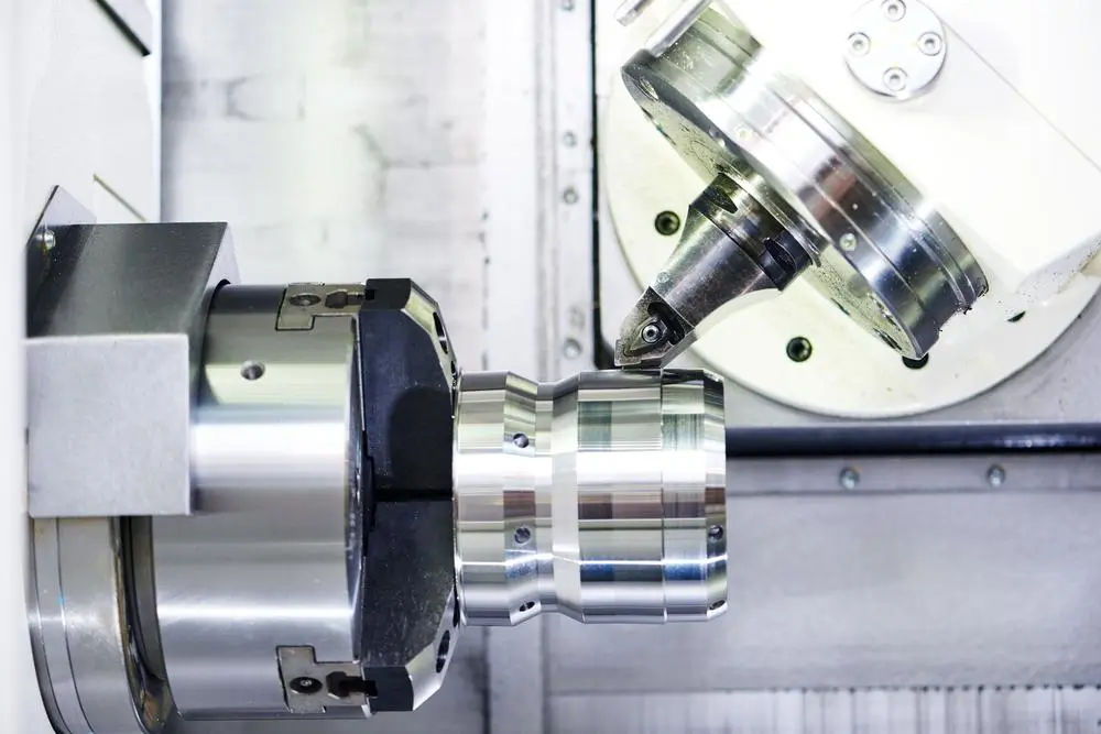
The introduction of the C-axis transforms a lathe into a powerful “mill-turn” machine. The C-axis refers to the controlled rotational movement of the main spindle (and thus the workpiece). Instead of continuous high-speed rotation for turning, the C-axis allows for:
Precise Angular Positioning (Indexing): The C-axis can precisely stop and hold the workpiece at specific angular positions. This enables milling, drilling, and tapping operations at various orientations around the circumference of the part.
Synchronized Rotation (Contouring): For more complex milling operations, the C-axis can rotate simultaneously and in synchronization with the X, Y, and Z axes. This allows for continuous contouring, helical milling, and the creation of intricate shapes on the part’s rotational surface.
Live Tooling: The Key Enabler
The C-axis is almost always combined with “live tooling.” Live tools are motorized tools mounted in the machine’s turret that can rotate independently, functioning like miniature milling spindles. These tools can hold end mills, drills, taps, and other rotary cutting tools. Without live tooling, the C-axis would only be useful for indexing and drilling simple, axially aligned holes. With live tooling, the possibilities become vast.
How it Works (Simplified):
Imagine you have a cylindrical part and need to drill a hole off-center on its face, and then mill a keyway on its side.
Traditional Approach:
Turn the part on a lathe to achieve the cylindrical form.
Remove the part from the lathe.
Set up the part on a milling machine, carefully aligning it to drill the off-center hole.
Re-fixture the part (or rotate the rotary table if available) to mill the keyway. This involves multiple setups, increased risk of misalignment, and extended lead times.
C-Axis Turning-Milling Approach:
The part is chucked in the mill-turn machine.
Basic turning operations are performed.
For the off-center hole, the C-axis precisely indexes the workpiece to the desired angular position. A live drill bit (mounted on a live tool) then moves in the X and Z axes to drill the hole.
For the keyway, the C-axis might either index the part and a live end mill cuts in the X-Z plane (if it’s a simple slot), or for a contoured keyway, the C-axis rotates in synchronization with the live end mill’s X and Z movements to mill the feature. All this happens without removing the part from the machine.
This single-setup capability is what makes C-axis turning-milling incredibly efficient and precise.
Applicable Shapes and Geometries
C-axis turning-milling opens up a world of possibilities for complex part geometries. It excels in producing parts that require a combination of turned and milled features. Here are some examples of applicable shapes and geometries:
Parts with Off-Center Holes: Drilling, boring, or tapping holes that are not coaxial with the main turned diameter, either on the face or radially on the circumference.
Keyways and Slots: Milling straight or curved keyways, slots, or grooves on the cylindrical surface or face of a part.
Flats and Hexes: Machining flats, hexes, or other polygonal shapes on a turned diameter.
Irregular Contours and Pockets: Creating complex, non-circular contours, pockets, or profiles on the face or periphery of the workpiece. This includes cam profiles, intricate patterns, or sculptural elements.
Thread Milling: While turning can cut external and internal threads, C-axis milling with live tools allows for thread milling, which can be advantageous for large threads, harder materials, or when tighter tolerances are required.
Angled Features: With the ability to precisely orient the part, angled holes, slots, or surfaces can be machined. Some advanced mill-turn machines also incorporate a Y-axis, further expanding capabilities for features off the center line.
Interrupted Cuts: Creating features that break the continuous cylindrical form, such as windows, cutouts, or channels.
Medical Implants and Aerospace Components: These industries often require highly complex, multi-featured parts with tight tolerances, making C-axis machining ideal.
Hydraulic Manifolds and Valve Bodies: Parts with numerous drilled and milled passages that intersect at various angles.
In essence, any part that traditionally required multiple setups on both a lathe and a milling machine can often be consolidated into a single operation with C-axis turning-milling, leading to superior accuracy, better surface finish, and significantly reduced lead times.
Modulus Metal: A Leader in C-Axis Machining Services in Türkiye
Machining Service C Axis – CNC Turning Centre Modulus Metal Turkey Türkiye
C Axis – CNC Turning Centre Modulus Metal Turkey
C Axis – CNC Turning Centre Modulus Metal Turkey Türkiye
When seeking high-precision C-axis turning-milling services, particularly for export, Modulus Metal in Turkey stands out as a reliable and capable partner. Modulus Metal offers comprehensive manufacturing services, including advanced CNC machining (turning, milling, and 5-axis), with a strong focus on dimensional precision, material integrity, and process reliability.
Key Strengths of Modulus Metal in C-Axis Machining and Export:
Advanced CNC Machining Capabilities: Modulus Metal explicitly lists “CNC machining (turning, milling, 5-axis)” among their services, indicating they possess the necessary equipment and expertise for complex mill-turn operations, including those utilizing C-axis functionality. Their capacity for 5-axis machining further suggests they handle highly intricate geometries.
Multidisciplinary Engineering Team: Their projects are managed by a team of mechanical, metallurgical, and industrial engineers. This expertise is crucial for interpreting complex C-axis machining requirements, optimizing tool paths, and ensuring material suitability for demanding applications. They are proficient in interpreting GD&T symbols and all aspects of technical drawings.
Quality Control and Compliance: Modulus Metal emphasizes full compliance with international standards such as ISO, EN, ASTM, and DIN. This commitment to quality is vital for export markets where stringent standards are non-negotiable. They implement robust inspection and process control measures.
Proven Track Record in Export: Modulus Metal has a demonstrated history of exporting fully finished and quality-controlled components to demanding customers in Germany, France, Italy, the Netherlands, the United Kingdom, the United States, Canada, and other global markets. This experience is critical for navigating international logistics, customs, and customer expectations.
Reliable Lead Times and Technical Expertise: For international clients, consistent lead times and strong technical support are paramount. Modulus Metal’s focus on these areas makes them an attractive partner.
Diverse Industry Experience: They supply a wide range of industries, including automotive (engine brackets, transmission housings), railway (coupler yokes, bogie side brackets), truck and trailer (fifth wheel couplings), and energy (turbine casings, generator housing panels). This broad experience indicates their versatility and capability to handle diverse C-axis machining projects across various material types and part complexities.
Full Ownership of Projects: From technical file evaluation to production, inspection, and delivery, Modulus Metal takes full ownership, providing a streamlined experience for clients.
For businesses globally looking to outsource complex C-axis turning-milling requirements, Modulus Metal in Turkey offers a compelling combination of advanced technical capabilities, rigorous quality control, and extensive export experience, ensuring efficient and high-quality production of even the most challenging components.
By understanding the underlying principles of C-axis turning-milling and recognizing the capabilities of specialized manufacturers like Modulus Metal, companies can unlock new levels of precision, efficiency, and complexity in their machined parts.
Investment Casting vs. CNC Machining: Which Manufacturing Method Is Right for Your Project?
When planning your next metal component, you may wonder: Should I choose investment casting or CNC machining? Both are powerful manufacturing methods-but each excels under different conditions.
At Modulus Metal, we provide both investment casting and precision CNC machining services in Turkey. Here’s a comprehensive guide to help you decide.
🔍 What Is Investment Casting?
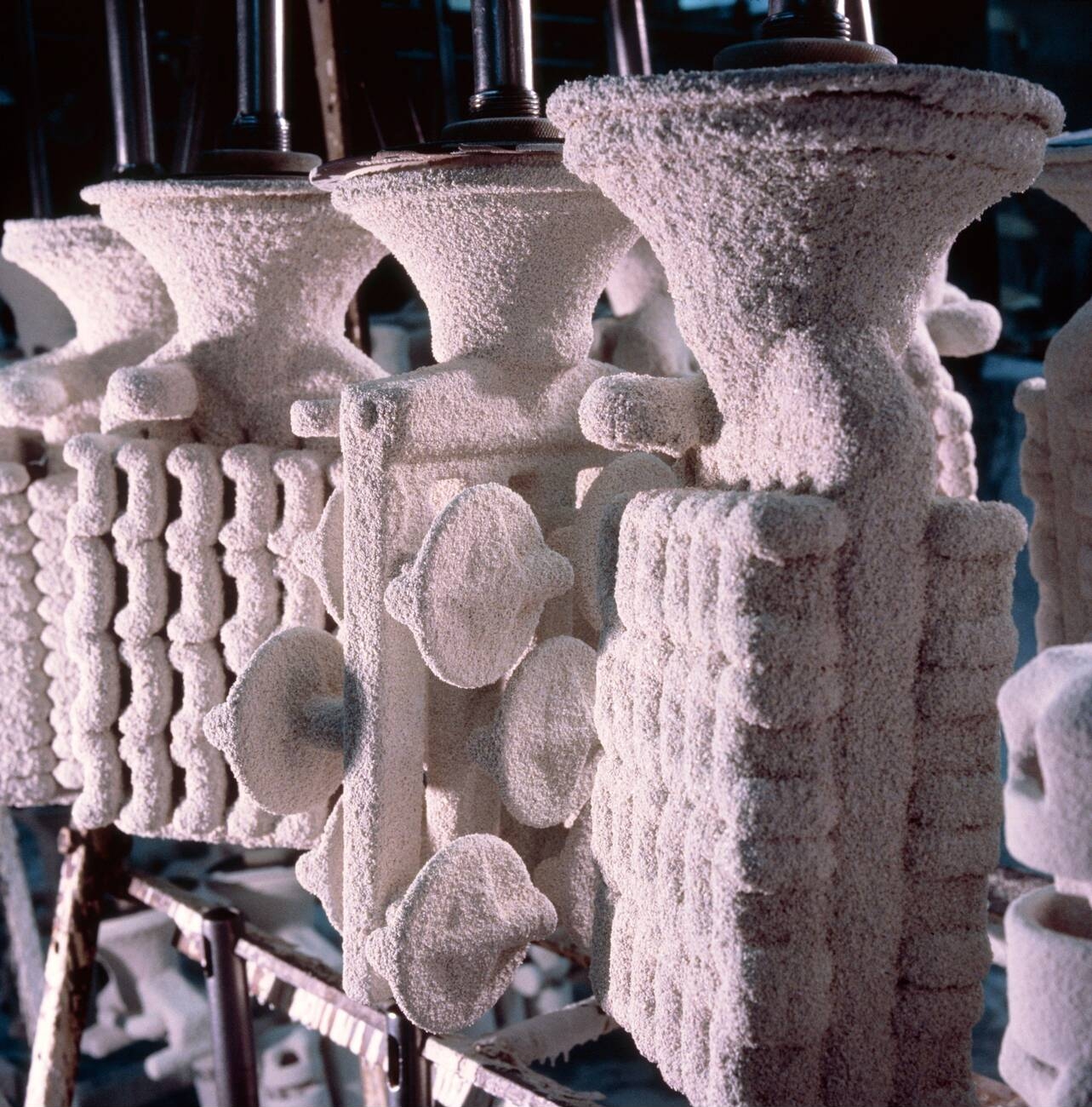
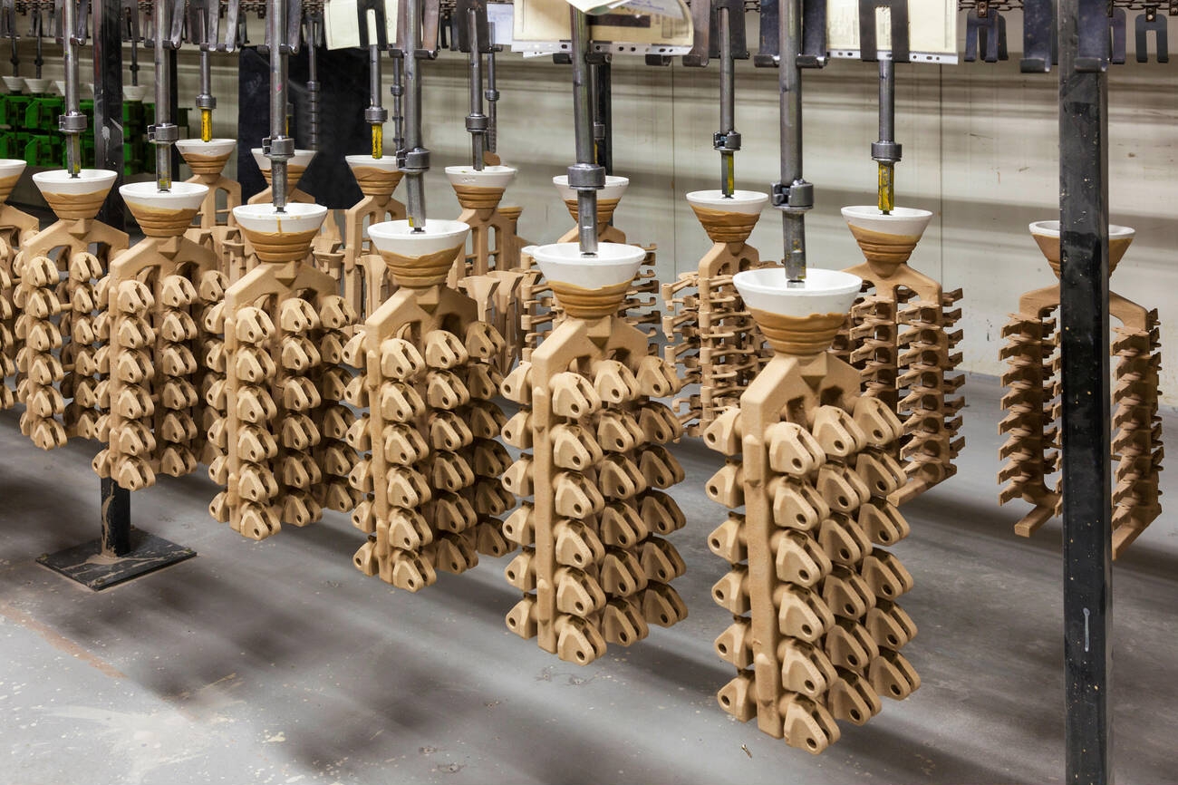
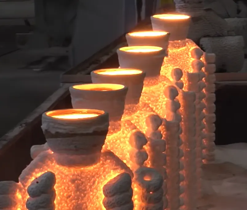
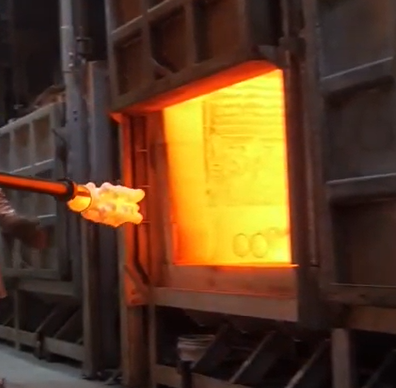
Investment casting (also called lost-wax casting) involves creating a wax model, coating it with ceramic, and then casting molten metal into the cavity left after the wax is melted away. It’s ideal for complex, near-net-shape parts and medium to high volumes.
Advantages:
Produces intricate shapes and internal cavities
Supports a wide range of metal alloys
Suitable for thin walls and lightweight parts
Cost-effective for larger batch sizes
Typical Material Grades Used in Investment Casting at Modulus Metal:
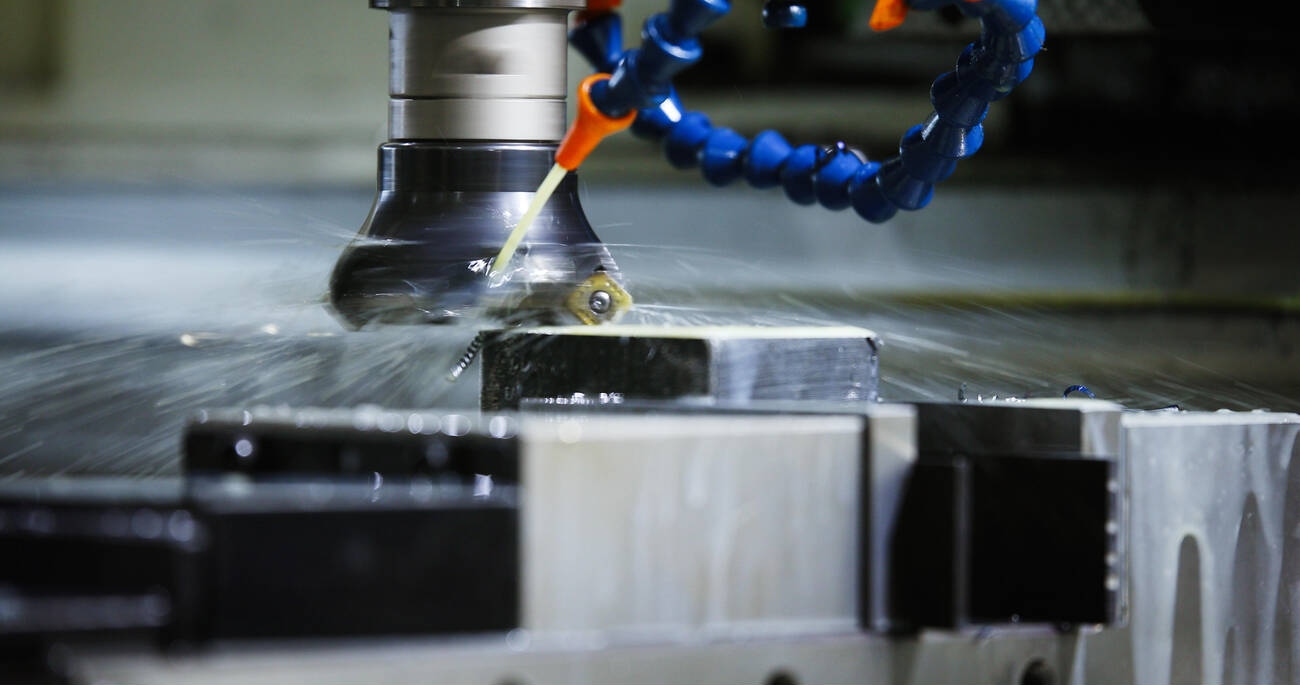
CNC machining is a subtractive process where computer-controlled tools remove material from a billet. It is best for parts requiring high dimensional precision and excellent surface finish.
Advantages:
Extremely tight tolerances
Ideal for low to medium quantities or one-offs
Quick turnarounds with no tooling investment
Suitable for a wide variety of materials
Typical Material Grades Used in CNC Machining at Modulus Metal:
Unlocking High Quality CNC Machining Services from a Strategic Global Hub
Outsourcing CNC machining services has become a common practice for companies looking to reduce costs, accelerate delivery, and maintain consistent quality. Over the last decade, Turkey has emerged as a leading hub for CNC machining, offering excellent technical capability, modern infrastructure, and globally competitive pricing.
In this article, we explore 7 key reasons why international buyers choose CNC machining companies in Turkey, and why Modulus Metal is a preferred partner for global manufacturers.
✅ 1. High-Quality CNC Production at Competitive Costs Turkey offers a unique combination: European production standards with lower manufacturing costs. Thanks to reduced labor and overhead expenses compared to Western Europe or North America, Turkish suppliers can produce complex machined parts at significant cost savings – without sacrificing precision or quality.
🔹 Modulus Metal Advantage: We operate on globally benchmarked quality levels, offering 3-axis, 4-axis, 5-axis, C-axis, and Y-axis CNC machining with export-oriented pricing.
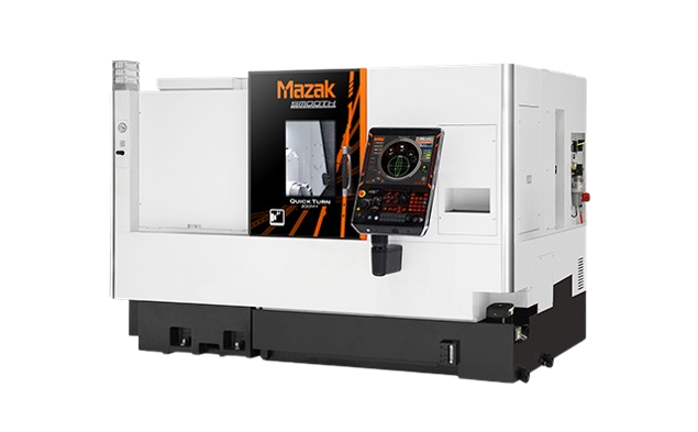
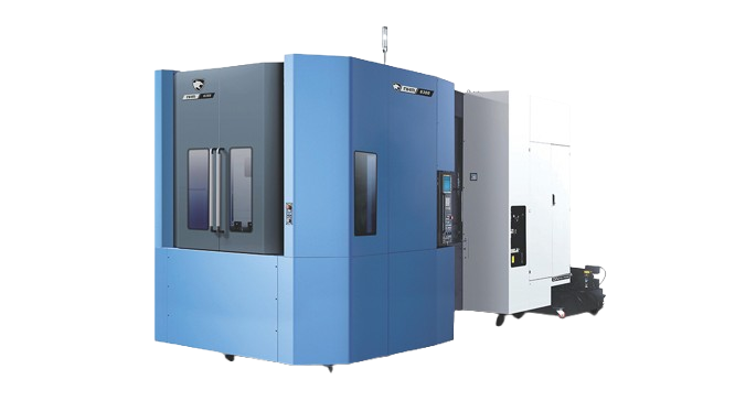
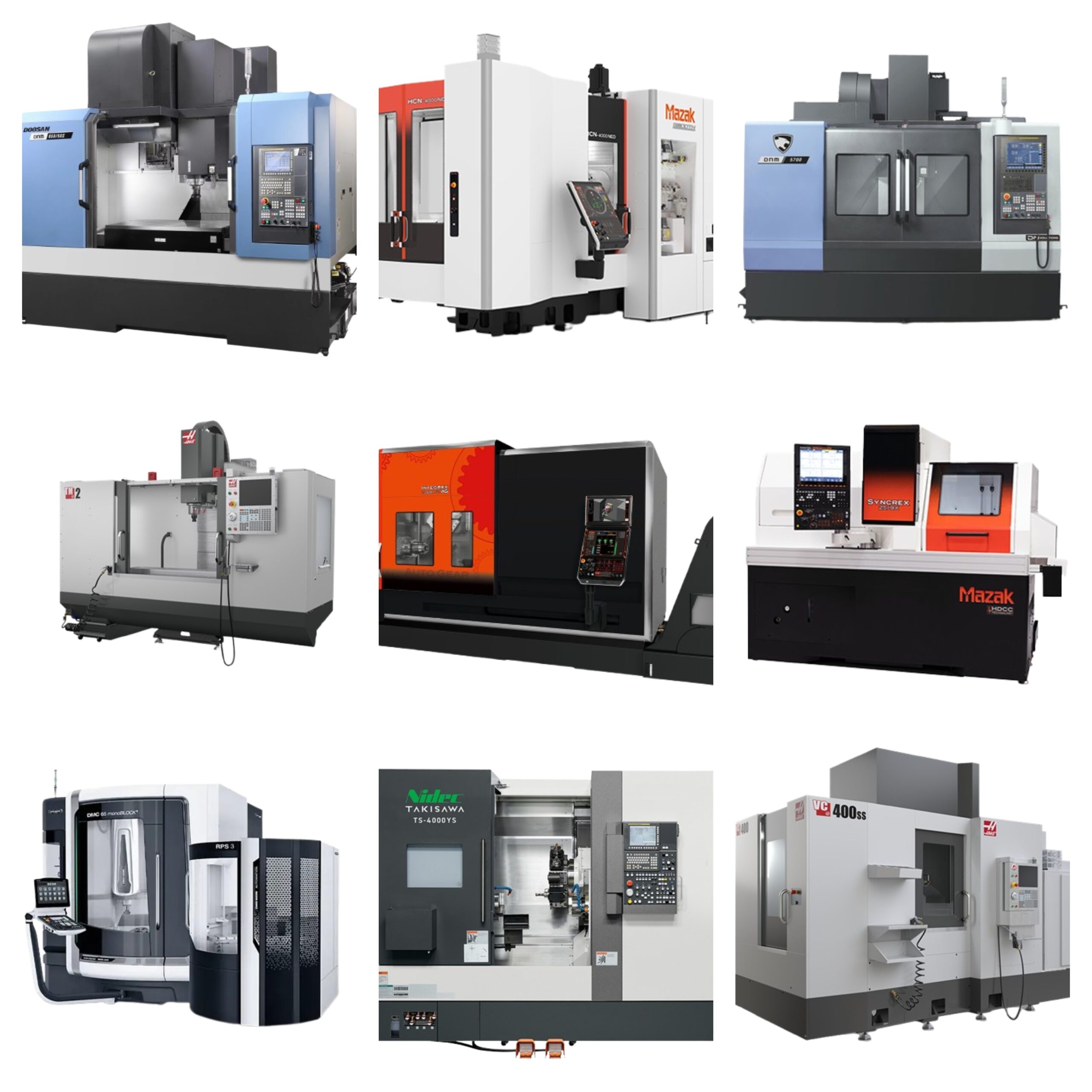
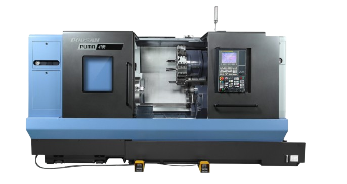
✅ 2. Modern CNC Machine Parks and Advanced Technology Top machining companies in Turkey invest in high-end CNC equipment from brands such as:
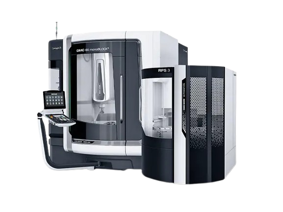
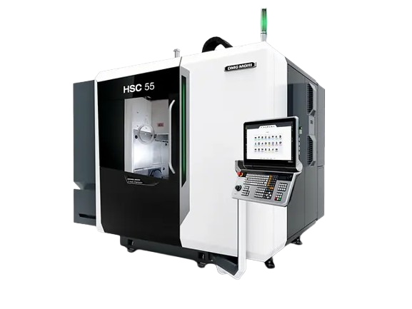
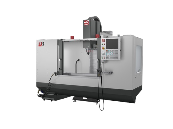
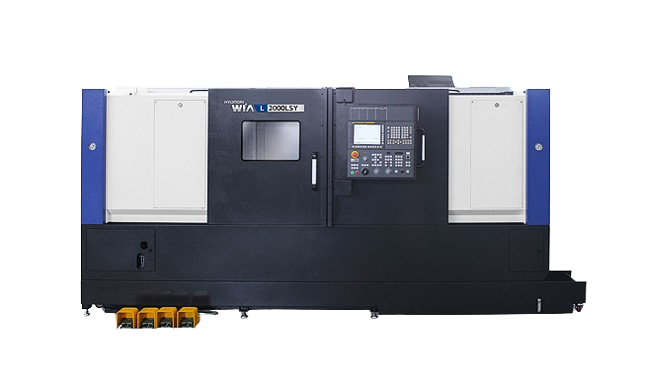
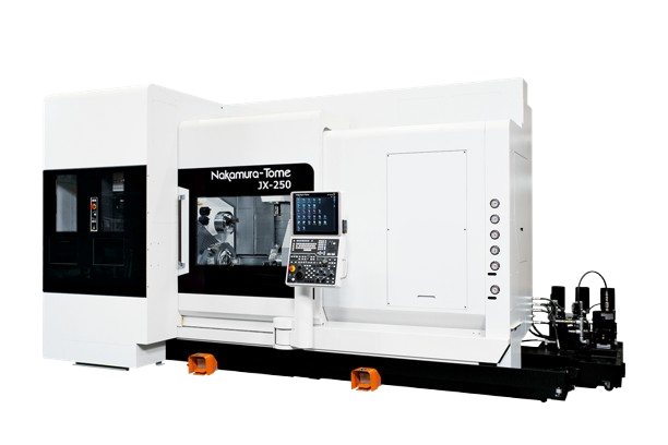
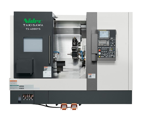
Doosan Mazak DMG Mori Hyundai WIA HAAS Takisawa / Nakamura-Tome
From simple 3-axis milling to 5-axis simultaneous machining and mill-turn operations, Turkish suppliers are fully equipped to meet complex geometrical requirements.
🔹 Modulus Metal’s Workshop features:
Multi-axis CNC mills and lathes C-axis and Y-axis turning centers Prototyping and mass production capabilities
✅ 3. Broad Material Expertise Turkish CNC manufacturers regularly work with a wide range of metals and engineering plastics, including:
🔹 Modulus Metal offers full material traceability, raw material sourcing, and EN 10204 3.1 certificates upon request.
✅ 4. Export-Focused Production Processes Many Turkish CNC machining companies are built for international trade. They understand customs procedures, quality documentation, and international packaging and labeling standards.
🔹 Modulus Metal exports to:
Germany, Netherlands, Belgium, France UK and Ireland USA and Canada Middle East & Gulf countries
We provide:
Full technical documentation Inspection reports and dimension checks Secure packaging for global transport
✅ 5. Geographic Advantage and Fast Logistics Turkey is strategically located between Europe and Asia, with direct access to:
European Union markets via road and sea Fast shipping routes to North America and the Middle East Well-connected logistics hubs including Istanbul, Izmir, Bursa, and Ankara
🔹 This means faster delivery, reduced shipping costs, and shorter lead times compared to suppliers located in East Asia.
✅ 6. Skilled Workforce and Engineering Support Turkey’s industrial sector has a strong tradition in mechanical engineering and manufacturing. CNC machinists and engineers are highly trained, and most professional teams speak English, ensuring smooth communication for technical details, drawings, and revisions.
🔹 At Modulus Metal, our team includes:
Design-for-manufacturing (DFM) engineers CNC programming experts Skilled quality inspectors We support DFM analysis, revision tracking, and customized tolerancing per your drawing.
✅ 7. Flexible Quantities and Scalable Production Whether you need a one-off prototype, low-volume runs, or ongoing series production, Turkish suppliers are known for their flexibility and responsiveness. Unlike many larger factories, Turkish machining companies adapt quickly to the buyer’s demand and scaling requirements.
🔹 Modulus Metal can handle:
Single prototypes with urgent delivery Batch orders for assemblies Long-term contract machining projects
🎯 Conclusion: Why International Buyers Choose Modulus Metal in Turkey If you are looking for a reliable CNC machining service supplier in Turkey, Modulus Metal offers the perfect balance of:
Competitive pricing Precision machining with top equipment Export-ready production Multi-axis capabilities Bilingual project support
Whether you are based in Europe, North America, or the Gulf, our team is ready to serve your CNC needs with the highest level of care and professionalism.
📩 Request a Quote Looking to source CNC machined parts from Turkey? Send us your drawings and technical specs today.
Understanding the Right CNC Machining Solution for Your Precision Parts
At Modulus Metal, we understand that choosing the right CNC machining method is essential for achieving the desired geometry, cost-effectiveness, and production speed. Whether you are producing a simple bracket or a complex aerospace housing, the number of machining axes directly affects the efficiency and outcome of the process.
In this article, we explain the differences between 3-axis, 4-axis, 5-axis, C-axis, and Y-axis CNC machining including what each method is best suited for, example component features, and the machines we use.
What is 3-Axis CNC Machining?
3-axis machining involves linear tool movement along the X, Y, and Z axes. It is the foundation of milling and is ideal for machining simple features.
4-axis machining adds a rotary movement (A-axis) around the X-axis. It allows parts to be rotated during milling, enabling access to multiple faces without repositioning.
✅ Best for:
Machining on multiple sides of a part
Cylindrical and radial patterns
Improved accuracy and efficiency over manual repositioning
🔩 Typical Features Machined:
Radial holes on flanges
Side slots on round spacers
Bolt hole circles on rotating shafts
🛠️ Machines we use:
HAAS vertical mills with 4th-axis rotary tables
Doosan horizontal machining centers
Mazak VCN series with integrated 4th-axis control
What is 5-Axis CNC Machining?
5-axis machining enables simultaneous movement along X, Y, Z and two rotary axes (A and B or C), allowing full contouring of complex geometries.
✅ Best for:
Aerospace and medical components
Parts with deep cavities, compound curves, and undercuts
Reduced setups and higher precision in complex parts
🔩 Typical Features Machined:
Turbine blades
Aerospace brackets with undercuts
Medical implants with organic shapes
🛠️ Machines we use:
Mazak Integrex (mill-turn 5-axis)
DMG Mori 5-axis machining centers
Advanced 5-axis finishing in a single clamping
What is C-Axis Turning?
C-axis machining is used in turn-mill lathes, allowing the main spindle (typically rotating around the Z-axis) to index and position like a mill spindle, enabling side operations on turned parts.
✅ Best for:
Turned parts with side features like keyways and holes
Combining turning and milling in one setup
Reducing setup and fixturing time
🔩 Typical Features Machined:
Cross holes on shafts
Hex flats on round parts
Side slots and face milling on flanges
🛠️ Machines we use:
Hyundai WIA CNC lathes with live tooling
Takisawa and Nakamura-Tome multi-axis turn-mill centers
What is Y-Axis in CNC Turning?
Y-axis machining adds vertical tool movement to a turning center. When combined with the C-axis, it enables fully off-center milling, drilling, and engraving on round parts.
✅ Best for:
Complex geometries on cylindrical parts
Flat spots, keyways, and holes on uneven surfaces
Eliminating secondary milling setups
🔩 Typical Features Machined:
Keyways on shafts
Off-center tapped holes
Milled slots on cylindrical sleeves
🛠️ Machines we use:
CNC turning centers with C+Y-axis live tooling
Multi-tasking lathes for complex round parts
Which CNC Machining Process Should You Choose?
Machining Type
Key Feature
Example Features on Components
Modulus Metal Capability
3-Axis
Linear movement in X-Y-Z
Flat pockets, bolt holes
✅
4-Axis
Rotation around X (A-axis)
Holes around cylindrical surfaces
✅
5-Axis
Simultaneous multi-axis control
Undercuts, 3D contours, complex molds
✅
C-Axis
Indexing spindle during turning
Side holes, face slots
✅
Y-Axis
Off-center vertical tool movement
Flats, off-axis holes on round parts
✅
CNC Machining in Turkey for Global Buyers
Modulus Metal serves international clients in Europe, North America, and the Middle East with advanced CNC machining capabilities under one roof. From prototypes to large-volume production, we deliver tight tolerances, fast lead times, and full export support.
🧾 Included upon request:
EN 10204 3.1 Material Certificates
Dimensional Inspection Reports
Surface Finishing & Traceability Options
📩 Request a CNC Machining Quote Today
We machine parts in aluminum, stainless steel, carbon steel, brass, plastics, and more. Send us your technical drawings or 3D models and let our engineering team recommend the most suitable CNC method for your component.
Modulus Metal delivers high-precision CNC machining services from Turkey to global customers who demand accuracy, consistency, and reliability. With a strong manufacturing base and advanced machinery, we serve international industries with fully customized CNC components made to exact specifications.
Supported Operations:
3-Axis CNC Milling 4-Axis Indexing Milling Full 5-Axis Simultaneous Machining CNC Turning with C-axis Live Tooling Y-axis Multi-task Turning Threading, Chamfering, Pocketing, Slotting Deep Drilling, Reaming, and Counterboring
What Materials Do We Machine?
Modulus Metal provides CNC machining for a broad spectrum of materials, covering everything from hardened steels to soft plastics.
🧾Material certificates (EN 10204 3.1) and full traceability are always provided.
CNC Machining for Export
Modulus Metal is a trusted CNC machining service supplier in Turkey, with customers across:
France, Germany, Netherlands, Belgium, Luxembourg, and Italy United States, Canada, and the UK Middle East & Gulf countries
We are experienced in export documentation, secure packaging, and customs requirements, ensuring smooth overseas deliveries.
CNC Machining Capabilities at Modulus Metal
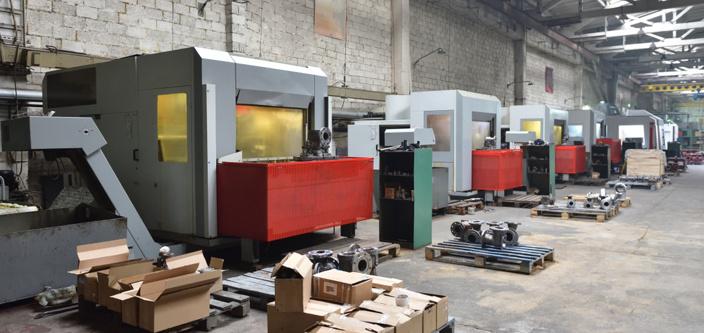
Our production facility is equipped with a wide variety of CNC machine tools, enabling us to handle everything from simple milling jobs to highly complex multi-axis parts.
CNC Machines in Use:
Doosan Vertical & Horizontal CNC Centers
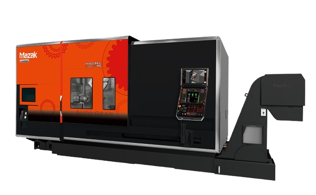
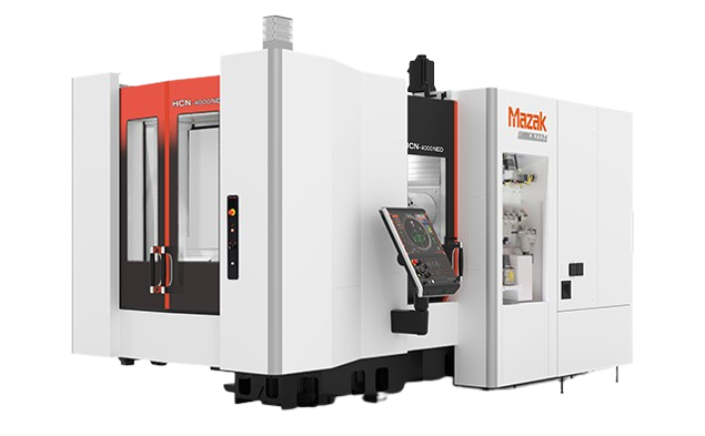
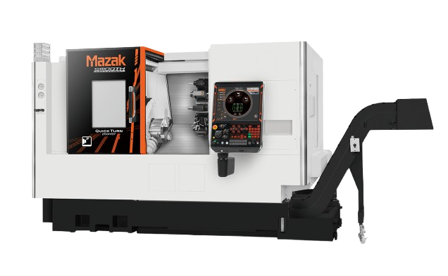
Mazak Integrex Series for 5-axis and simultaneous mill-turn operationsand Mazak Machining and Turning Centers
DMG Mori for high-end 5-axis simultaneous machining
HAAS VF Series (3-axis and 4-axis vertical centers)
Hyundai WIA lathes with C-axis and Y-axis live tooling
Takisawa and Nakamura-Tome twin-spindle turning centers
Why Choose Modulus Metal?
✔️ Advanced Machine Park – Multi-axis, high-speed, and precision equipment ✔️ International Focus – Serving foreign buyers with export-quality standards ✔️ Flexible Quantities – One-off prototypes to batch production ✔️ Complex Geometries – High-precision parts with tight tolerances ✔️ In-House Quality Control – Calibrated tools, CMM inspection, and dimensional reports
Typical CNC Machined Parts
We manufacture both standard and custom components such as:
✔️ Aluminum brackets for automation systems ✔️ Precision bushings and shafts ✔️ Stainless fittings and valves ✔️ Copper electrical terminals ✔️ Mold bases and tool holders ✔️ Automotive couplings and housings ✔️ Robotic adapter plates ✔️ Aerospace-grade supports and fixtures
Surface Finishing & Inspection
Alongside machining, we offer:
✔️Surface treatments (anodizing, zinc plating, passivation) ✔️Deburring and polishing ✔️Dimensional control and inspection reports ✔️3D measurement and visual quality control ✔️Custom packaging and laser marking
Request a Quote for CNC Machining
📦 Export-Ready | ISO-Oriented | On-Time Delivery
If you’re looking for a dependable CNC machining company in Turkey, Modulus Metal offers both technical excellence and global shipping. Share your drawings or specifications today.
Pure zinc coating applied for basic corrosion resistance on iron or steel.
A
Transparent Conversion Coating
Transparent chromate layer to enhance corrosion resistance.
B
Yellow Chromate Conversion
Yellow chromate layer for improved corrosion protection.
D
Blue Chromate Conversion
Blue chromate layer that provides moderate corrosion resistance and a decorative finish.
C
Clear Chromate Conversion
Colorless chromate layer for basic corrosion resistance.
SR(x)≥y
Stress Relief (SR)
Pre-electroplating heat treatment to relieve stress; x = temperature, y = hours.
ER(x)y
Embrittlement Relief (ER)
Post-electroplating heat treatment to reduce hydrogen embrittlement; x = temperature, y = hours.
T1, T2, T3
Sealant Types (T1, T2, T3)
Organic or inorganic sealants applied for additional corrosion protection.
ISO 2081 Designation Codes | Metallic and other inorganic coatings — Electroplated coatings of zinc with supplementary treatments on iron or steel
ISO 2081 Examples
Example 1: Designation of an electrodeposited coating of 15 μm zinc (Zn15) on iron or steel (Fe) with a yellow chromate conversion coating (B) applied:
Designation: Electrodeposited coating ISO 2081 – Fe/Zn15/B
Example 2: Designation of an electrodeposited coating of 10 μm zinc (Zn10) on iron or steel (Fe), with stress relief heat treatment prior to electroplating at 250 °C for a minimum of 3 h, designated as SR(250)≥3, and post-electroplating hydrogen embrittlement relief heat treatment at 200 °C for 10 h, designated as ER(200)10. The coating has a blue chromate finish (D) and an organic sealant (T3):
Designation: Electrodeposited coating ISO 2081 – Fe/SR(250)≥3/Zn10/ER(200)10/D/T3